Written By Mr Lam on Tuesday, January 1, 2013 | 8:12 PM
See Animation : Cutting Machine
Cutting Machine :
Detail Cutting Machine :
Notes : LS = Limit Switch. LS 1 = Limit Switch for Cutter Reverse. LS 2 = Limit Switch for Cutter Forward. LS 3 = Limit Switch for Clamp1 (Fixed) Forward (Clamp). LS 4 = Limit Switch for Clamp1 (Fixed) Reverse (UnClamp). LS 5 = Limit Switch for Clamp2 (Movable) Forward (Clamp). LS 6 = Limit Switch for Clamp2 (Movable) Reverse (UnClamp). LS 7 = Limit Switch for Clamp2 (Movable) Forward. LS 8 = Limit Switch for Clamp2 (Movable) Reverse.
Number Of Inputs and Output PLC applied : 1. Number Of Inputs PLC is 11 Input : --- 1 Unit Input for Push Button Start. --- 1 Unit Input for Push Button Emg / Emergency. --- 1 Unit Input for Selector Switch Electric Motor ON. --- 8 Unit Input for Limit Switch (LS). --- Total Number Of Inputs PLC is Minimum 11 Input Unit.
2. Number Of Output PLC is 9 Output : --- 1 Unit Output for Contactor. It's Functions to electrical Motor Cutter ( ON / OFF Motor ) . --- 2 Unit Output for SolenoidCylinder Cutter : Forward - Reverse. --- 2 Unit Output for Solenoid Cylinder Clamp1 : Clamp - UnClamp . --- 2 Unit Output for Solenoid Cylinder Clamp2 : Clamp - UnClamp. --- 2 Unit Output for Solenoid Cylinder Clamp2 : Forward - Reverse. --- Total Number Of Outputs PLC is Minimum 9 Output Unit.
Step 1 : a. If Push Button Emg = OFF Then All System OFF. b. If LS 1 = ON And LS 4 = ON And LS 6 = ON And LS 8 = ON Then All Limit Switch Origin = ON. c. If Push Button Emg = ON And Selector Switch Motor = ( OFF to ON ) And All Limit Switch Origin = ON Then Contactor Motor = ON.
Step 2 : a. If Push Button Start = ON And Contactor Motor = ON And All Limit Switch Origin = ON Then Starts Automatic Cutting Process. --- Download Animation : Cutting Machine b. If have been three times ( Data Setting = 3 (Can be Changed) ) Then Stops Automatic Cutting Process And ALL Return Origin. c. If Push Button Emg = Pulse ON Then ALL Return Origin. Source: http://program-plc.blogspot.com/2009/08/plc-for-automatic-cutting-machines.html
Remarks : 1. Movement1 : Cylinder Clamp Left AND Right to Middle 2. Movement2 : Cylinder Ejector Down 3. Movement3 : Cylinder Clamp Left AND Right to Forward 4. Movement4 : Cylinder Nozzle to Middle 5. Movement5 : Cylinder Nozzle to Forward AND Welding Torch=ON 6. Movement6 : Cylinder Nozzle to Middle 7. Movement7 : Cylinder Nozzle to Reverse 8. Movement8 : Cylinder Clamp Left AND Right to Middle 9. Movement9 : Cylinder Clamp Left AND Right to Reverse 10. Movement10 : Cylinder Ejector Up
The results of welding product
Detail of Automatic Welding Machine
Legend for Detail of Automatic Welding Machine: 1. Raw Material for Welding 2a/2b. Push Button Start (Normally Open Contact) 2a. Start-1 (PB1) 2b. Start-2 (PB2) NOTE: Push Button Start-1(PB1) And Push Button Start-2(PB2) Connected in Series 3a/3b. Safety Sensor 3a. Safety Sensor Receiver 3b. Safety Sensor Transmitter NOTE: If NO OBJECT Then Safety Sensor=ON Else Safety Sensor=OFF 4. Cylinder Clamp Left 5. Cylinder Clamp Right 6. Limit Switch (LS) Clamp Left Reverse 7. Limit Switch (LS) Clamp Left Middle 8. Limit Switch (LS) Clamp Left Forward 9. Limit Switch (LS) Clamp Right Reverse 10. Limit Switch (LS) Clamp Right Middle 11. Limit Switch (LS) Clamp Right Forward 12. Cylinder Ejector 13. Cylinder Nozzle (for welding nozzle) 14. Limit Switch (LS) Ejector Up 15. Limit Switch (LS) Ejector Down 16. Limit Switch (LS) Nozzle Reverse 17. Limit Switch (LS) Nozzle Middle 18. Limit Switch (LS) Nozzle Forward 19. Welding Machine, such as GMAW(Gas Metal Arc. Welding) 20. Panel Box 21. Welding Nozzle / Welding Gun / Welding Torch
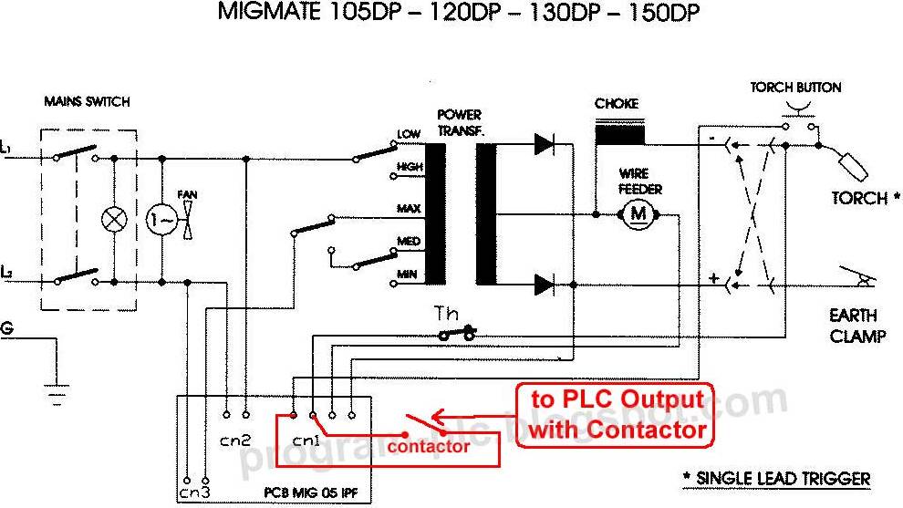
Example GMAW Welding: use MIG Welding Circuit diagram of MIG Welding to PLC Output with contactor Contactor coil to PLC Output and Contactor contact (NO) to Torch Button of MIG Welding
PLC Input and Output Devices : 1.PLC Input : <-> 1 Input for Emergency Stop Button <-> 1 Input for Push Button Start <-> 1 Input for Safety Sensor <-> 1 Input for Limit Switch Clamp Left Reverse <-> 1 Input for Limit Switch Clamp Left Middle <-> 1 Input for Limit Switch Clamp Left Forward <-> 1 Input for Limit Switch Clamp Right Reverse <-> 1 Input for Limit Switch Clamp Right Middle <-> 1 Input for Limit Switch Clamp Right Forward <-> 1 Input for Limit Switch Ejector Up <-> 1 Input for Limit Switch Ejector Down <-> 1 Input for Limit Switch Nozzle Reverse <-> 1 Input for Limit Switch Nozzle Middle <-> 1 Input for Limit Switch Nozzle Forward --> Total PLC Input, minimum of 14 Input.
2.PLC Output : <-> 1 Output for Contactor to Torch Button of MIG Welding <-> 1 Output for Solenoid to Clamp Left Reverse <-> 1 Output for Solenoid to Clamp Left Forward <-> 1 Output for Solenoid to Clamp Right Reverse <-> 1 Output for Solenoid to Clamp Right Forward <-> 1 Output for Solenoid to Ejector Up <-> 1 Output for Solenoid to Ejector Down <-> 1 Output for Solenoid to Nozzle Reverse <-> 1 Output for Solenoid to Nozzle Forward --> Total PLC output, minimum of 9 Output.
NOTE: All Solenoid using Double Solenoid,3 Position ( 4/3 ways or 5/3 ways ),Closed Center
1. INPUT CONDITION : a. Waiting Start (Output Controller1) = ON, If: a.1. Emergency Stop = ON b.2. Waiting Start = OFF AND Safety Sensor = OFF
b. All Origin = ON, If: b.1. Emergency Stop = OFF b.2. Safety Sensor = ON b.3. Limit Switch Clamp Left Reverse = ON b.4. Limit Switch Clamp Right Reverse = ON b.5. Limit Switch Ejector Up = ON b.6. Limit Switch Nozzle Reverse = ON
c. Start = ON, If: c.1. Emergency Stop = OFF c.2. Safety Sensor = ON c.3. Push Button Start = ON
2. TRIGGER AND SENSOR CONDITION : a. Waiting Start / Output Controller1: All Origin AND Start b. Movement1 / Output Controller2: Cylinder Clamp Left AND Right to Middle c. Movement2 / Output Controller3: Cylinder Ejector Down d. Movement3 / Output Controller4: Cylinder Clamp Left AND Right to Forward e. Movement4 / Output Controller5: Cylinder Nozzle to Middle f. Movement5 / Output Controller6: Cylinder Nozzle to Forward ANDWelding Torch=ON g. Movement6 / Output Controller7: Cylinder Nozzle to Middle h. Movement7 / Output Controller8: Cylinder Nozzle to Reverse i. Movement8 / Output Controller9: Cylinder Clamp Left AND Right to Middle j. Movement9 / Output Controller10: Cylinder Clamp Left AND Right to Reverse k. Movement10 / Output Controller11: Cylinder Ejector Up
3. OUTPUT CONDITION : a. Use Internal Relay for the output: a.1. If Output Controller (2 or 9) = ON AND LS Clamp Middle (Left/Right) = ON Then LS Clamp Middle (Left/Right) = HOLD ON a.2 If Output Controller (3 or 10 or 1) = ON Then LS Clamp Middle (Left/Right) = HOLD OFF b. Output Controller 2 AND HOLD ON LS Middle for Solenoid Clamp Left Forward c. Output Controller 2 AND HOLD ON LS Middle for Solenoid Clamp Right Forward d. Output Controller 3 for Solenoid Ejector Down e. Output Controller 4 for Solenoid Clamp Left Forward f. Output Controller 4 for Solenoid Clamp Right Forward g. Output Controller 5 for Solenoid Nozzle Forward h. Output Controller 6 for Solenoid Nozzle Forward i. Output Controller 6 for Contactor Welding Torch=ON j. Output Controller 7 for Solenoid Nozzle Reverse k. Output Controller 8 for Solenoid Nozzle Reverse l. Output Controller 9 AND HOLD ON LS Middle for Solenoid Clamp Left Reverse m. Output Controller 9 AND HOLD ON LS Middle for Solenoid Clamp Right Reverse n. Output Controller 10 for Solenoid Clamp Left Reverse o. Output Controller 10 for Solenoid Clamp Right Reverse p. Output Controller 11 for Solenoid Ejector Up
4. CONTROLLER : Using 11 Output Controller : total movement = 10 movement Waiting Start = 1 Total Output Controller = 10 + 1 = 11