Latest Post

Alanog input How to it work

Written By Mr Lam on Wednesday, May 16, 2012 | 1:03 AM


In operating and monitoring the PLC system and computer, sometimes people have to deal with analog input. There’re basic differences of the analog input and the digital input and the implementation is quite different from one another. So how does the analog input work, anyway? 

Analog Input: Understanding It
Unlike the digital input, the analog input is using some kind of volume control system. In digital signals, the control is using binary codes of 0 and 1. Since the analog input is using volume controls, the value can range between 0 and full scale mode. These values will be interpreted by the PLC as integer value. The analog signal uses current of voltage mode – depending on which one is used by the system – with proportional magnitude that goes along with the whole processing value signals. For instance, a 0-10V analog input from 4-20mA would be changed into integer 0-32767 value. That’s how the analog input works. 

Analog Input: How to Make it Running
People need to keep the continuous value voltage sampled in order to do the analog input. Once the value is sampled, then it will be converted into numeric values by ADC or Analog to Digital Converter. The sampling process isn’t instant because each sample has to have a starting and stopping time. That’s why it’s called as sampling time because each sample does require certain time to complete. Sampling period is the time between each sample. Sampling period is often bigger than the sample time. Analog input can be used in any industrial use and implementation, but this type of input is usually done and implemented in: 
• Music recording. Music technology is using the integral part of ADC. When music production has been completed on the computers, the ADC is needed to make data stream that will be kept on digital file or compact disc. This type of input is also common when used in TV or radio broadcasting. 
• Signal digital process. When the analog signal has to be converted or processed, and then stored, or transported in the form of digital data, a fast ADC converter is usually used, like the one used in a TV tuner card, where the microcontrollers of 8 bit, 10, 12, and 16 bit are used. But it’s also possible to use fast ADC for certain applications, such as software defining radio application using the oscilloscopes digital storage. That’s the main basic of analog input, signal, and its implementation. 

Communication Setting for PLC Mitsubishi

For Communication Setting for PLC Mitsubishi on SoftwarePLC GX Developer, Step by Step :
Step 1
Open Software PLC Mitsubishi GX Developer 
Software PLC Mitsubishi GX Developer
Step 2 
Click Online --> Click Tranfer setup ... 
Online Tranfer setup
Step 3 
Show Menu Connection Setup 
Click icon Serial 
Show Dialog Box " PC side I/F Serial setting" 
Icon Serial
Step 4 
Show Dialog Box " PC side I/F Serial setting" 
Select COM Port --> Select Transmission speed --> Click OK Button 
PC side I/F Serial setting
Step 5 
Display Menu Connection Setup 
Click Connection test Button 
If Communication OK Then Show Dialog Box "Successfully connected with the .... ( PLC Type )---> Click OK Button
Display Menu Connection Setup ---> Click OK Button
Successfully connected

Download Program Ladder Diagram from PC to PLCMitsubishi

 Pls follow Step bellow
For Download Program Ladder Diagram from PC to PLCMitsubishi, Step by Step :
Step 1
Software PLC Mitsubishi, Open Software GX Developer 
Software GX Developer
Step 2 
Click Project --> Click Open Project... ( Ctrl + O) 
And Show Open Dialog 
Click Open Project
OR 
Step 2 
Click Icon Open Project 
And Show Open Dialog 
Click Icon Open Project
Step 3 
If Show Open Dialog Then Select Project Name --> 
After the Porject Name has been Selected --> 
Click Open Button
Select Project Name
Step 4
If Lader Diagram is Open Then : 
Click Online --> Click Write to PLC ... 
Write to PLC
Step 5
Menu Write to PLC 
Click Param+Prog --> Click Execute Button 
Show Dialog Box "Execute write to PLC" --> Click Yes Button 
Execute write to PLC
Step 6
Menu Write to PLC 
Waiting Write to PLC --> 
Writing... Parameter --> Writing... Program MAIN
Waiting Write to PLC
Step 7
Menu Write to PLC 
Show Dialog Box "Completed." --> Click OK Button --> 
Click Close on Menu Write PLC
Process Write to PLC has been Finish
Close on Menu Write PLC(source : http://program-plc.blogspot.com)

Solutions – Safety

Written By Mr Lam on Friday, May 4, 2012 | 12:47 AM


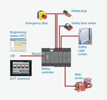
The MELSEC WS Safety Controller provides a cost effective way to add a safety controller capability to individual machines, or smaller scale systems. Mitsubishi Electric is proud to announce that the WS is a joint development with SICK AG of Germany, an acknowledged leader in the global machine safety industry. Its compact size insures easy placement in most control cabinets, without adding extra cost. Configuration saves engineering time by using a graphical icon based method, and program development and certification is simplified by the use of safety function blocks. For more complex needs, the WS is also scalable by simply adding additional I/O modules. Finally, integration with conventional control systems is easily achieved with the CC-Link open network connection or Ethernet.

Specifications

WS Safety Controller
I/O capacity
144 points (single channel)/72 points (dual channel)
Program memory capacity
Up to 255 function blocks
I/O
Modular units (up to 18), single or dual channel
I/O types available
DC safety in & out, safety relay out
Diagnostic capabilities
Internal state monitoring, execution error history
Network connectivity
CC-Link, Ethernet, EFI (direct communication with SICK safety devices)
Safety certifications
IEC 61508 SIL 3, ISO13849-1 PL e (EN 954 Category 4)

Compact PLC – MELSEC FX1N


The controllers of the FX1S series deliver outstanding functionality with up to 30 inputs and outputs in a very compact package. The FX1S is ideal for applications in difficult-to-access installations and systems where normal servicing is not possible. The integrated real-time clock and maintenance-free EEPROM with capacity for up to 2,000 program steps make the FX1S an autonomous and very service-friendly system.
FX1S series highlights:
  • 10 to 30 inputs and outputs
  • High processing speed (0.55µs per log. instruction)
  • Ample program storage space and large device ranges · Integrated positioning controller
  • Serial communications options (RS-232, RD-422, RS-485)
  • Analog signal processing with optional expansion adapters
  • Integrated real-time clock
  • User-friendly programming with MS Windows-based programming software package or hand-held programming unit
  • Expandable with adapters or display modules
Product range
Type
FX1S-10M
FX1S-14M
FX1S-20M
FX1S-30M
Power supply
100-240V AC / 24V DC
No. of inputs
6
8
12
16
No. of outputs
4
6
8
14
Digital outputs
Relay / Transistor
Program cycle period per logical instruction
0.55 - 0.7 µs
User memory
2000 steps EEPROM (internal)
Dimensions in mm (WxHxD)
60x90x75
60x90x75
75x90x75
100x90x75

MELSOFT-Software – GX IEC Developer


GX IEC Developer is more than a powerful IEC 1131.3 programming and documenation package. It supports your entire MELSEC PLC impleentation from the initial project planning to everyday operation, with a wealth of advanced functions that will help you to cut costs and increase your productivity.
The sophisticated program architecture comes with a range of new, user-friendly functions, including structured programming and support for function libraries.

Top-down application architecture
During the planning phase GX IEC Developer's structuring tools help you to organise your project efficiently: Use the intuitive graphical tools to identify and display tasks, functional units, dependencies, procedures and application structures. In addition to making your work easier, this also significantly reduces error frequency in later project stages.
Flexible implementation
In the engineering phase you then choose the programming language that best matches the structure of your project.
Program frequently-used functions in function blocks and organise them in libraries. This gives you the confidence that comes with knowing you are using tested, reliable code. Password support helps you to protect your valuable expertise.
Simple configuration of control components
Configuration of controller components is performed quickly and efficiently in tables with interactive dialogs and graphical support. And this powerful support is available for standard and special function modules as well as for the controller CPUs. You no longer have to create application programs to configure your system.
Setting up the hardware and network configuration
Powerful testing and debugging tools provide information on the current status of the controllers and the network you are connected to. Network functions like status and error displays, remote SET/RST functions for controllers and peripherals, Live List, Cycle Time, Connection State and more enable you to locate and correct errors quickly and get your hardware and networks up and running in record time.
Setting up the application program
GX IEC Developer comes with everything you need to get your applications installed, set up and running as quickly as possible, including comprehensive online programming functions, fast and informative monitoring displays, the ability to manipulate device values with the graphical editors, manual and automatic step mode execution in IL, the display of manipulated device values in the EDM (Entry Data Monitor) and much more.
Normal operation
During normal daily operation you can also use GX IEC Developer to display important system status information, either in stand-alone mode or called by another program in the control room.
Installation and maintenance
Top-down architecture, structured programming, comprehensive printed documentation and support for user-defined help for your function blocks all help to reduce the learning curve. You can make the information needed for installing and maintaining the system available to the operators quickly and efficiently, with minimum training overheads.
Key features include:
  • Powerful "Top-down" development environment
  • Total overview of PLC project and resources
  • Suited to large and complex projects
  • One programming software for modular and compact PLCs (Q/A and FX Series)
  • Flexible program development
  • Superior program documentation for easy understanding
  • State-of-the-art PC software technology acc. to IEC 1131.3
  • Programming languages FBD, AWL, KOP, AS and STC
  • Powerful offline simulation
  • Online program modification
  • Function blocks (FB, FC)
  • Libraries Minimum downtimes
  •  (source : http://www.mitsubishi-automation.com/)
 
Support : Creating Website | Johny Template | Mas Template
Copyright © 2011. Programs-Training PLCs - All Rights Reserved
Template Created by Creating Website
Proudly powered by Premium Blogger Template